top of page


Wallace G1
Overview of Assembly
Y Frame Assembly
X Carriage Assemble
Completed 3D printer (mechanical)
Z Axis, Linear Rails and 22 degree brackets
Base Assembly
Y Carriage Assembly
Parts for this section
-
Plastic parts
Y Motor Mount
X End Left
X End Right
X Carriage
2x X Rack Mounts
TR Lower Bed Mount
TF Lower Bed
Mount
Arduino Mount
Motor Blocks
X Axis and X Carriage
X Axis and X Carriage


Y Carriage Rack Assembly


Y Motor and Y Carriage Assembly


Z Motors and Z Axis Assembly
Filament Hooks


4x Flex Coupler for Z Axis
4x Spring Top
TF Right Bed Mount
TF Right
TF Left
2x Pinion
TF Left Bed Mount
2x Rack


Y Bearing Holder
Y Bearing Switch Holder
Y Bearing Holder 2
Y Bearing Switch Holder 2
Bed Foot
Foot Hook
2x Base End
Motor Foot


Motor Spacers
Hook Top for Spool
Filament Guide
Z Top Clamps
4x Feet
End Stop


-
Plastic parts:
-
X carriage
-
Rack
-
X End Left
-
X End Right
-
-
Thermistor
-
7x LM88 bearings
-
2x M3 x 35mm screws
-
1x M3 x 10mm screws
-
3x M3 nuts
-
1x 3/8" x 200mm threaded rod
-
2x 3/8" nuts
-
2x 8mm x 200mm smooth rods
-
Plastic parts:
-
TL Lower Bed Mount
-
TR Lower Bed Mount
-
Rack
-
Pinon
-
-
3/8" x 200mm threaded rod
-
2x 3/8" nuts
-
4x LM88 bearings
-
2x 8mm x 200mm smooth rods
-
1x M3 x 10mm screws


Motor Blocks
-
Plastic parts:
-
2x Base End
-
-
4x M3 x 10mm screws
-
4x M3 nuts
-
2x 8mm x 200mm smooth rods


Footing Assembly
-
Assembled Components:
-
2x Motor blocks
-
-
Plastic parts:
-
2x Bed Foot
-
Y Motor Mount
-
Y Bearing Holder
-
Y Bearing Holder 2
-
Y Bearing Switch
-
Y Bearing Switch 2
-
-
20x 3/8" nuts
-
20x 3/8" washers
-
Assembled Components:
-
Footing Assembly
-
Y Carriage Rack Assembly
-
-
Plastic parts:
-
Pinon
-
Motor spacer
-
-
3x M3 8mm screws
-
M3 nut
-
Nema 17 stepper motor
-
Plastic parts:
-
4x Motor spacers
-
Motor foot
-
Hook foot
-
Hook Top (spool holer)
-
-
8x M3 x 10mm screws
-
8x M3 nuts
-
8x M3 washers
-
2x Nema 17 stepper motors
-
Plastic parts:
-
-
2x Z top clamps
-
Y Motor Mount
-
Filament Guide
-
-
4x 3/8" nuts
-
3/8" x 200mm threaded rod
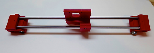
Take the "X End Left" plastic part and insert 2x LMU88 linear bearing, one on top of each other in the cylindrical hole. Repeat the exercise using the and the "X End Right" plastic part and the other 2x LMU88 linear bearings.
Once assembled the components should look like this.
Now take the "X carriage" plastic part and insert 3x LMU88 linear bearing. Insert two of the linear bearings on top of each other in the deeper hole. Insert the remaining bearing in the other hole.
Insert the 2x 8mm x 200mm smooth rods in each of the LMU88 linear bearings. The X carriage will slide along these and will be guided by these rails when printing.
Fasten the linear bearnings in the X carriage by inserting and tightening the M3 x 10mm screw in one side of the X carriage and placing the M3 nut in the opposit side. Once one, the linear bearing should hold in place.
Repeat the exercise with the "X End Left" and the "X End Right" plastic parts. To fasten the linear bearnings in the these parts insert and tightening an M3 x 35mm screw in one side of the "X End Left" and placing the M3 nut in the opposit side. Next insert an M3 x 35mm screw in one side of the "X End Right" and the M3 nut in the other. Once one, the linear bearing should hold in place.
Place one of the 3/8" nut in the hexagonal hole in the "X End Left" as shown,
bottom of page